

- Home
- Companies
- Lohmeyer GmbH
- Articles
- Determination of the Substitute ...
Determination of the Substitute Anemometer Position for AUSTAL When Using Wind and Turbulence Fields from MISKAM
For dispersion calculations in accordance with the Technical Instructions on Air Quality Control (TA-Luft), meteorological data is generally used that is either measured at the site or, if no on-site measurements are available, transferred there (QPR) or based on model calculations.
Meteorological data has to be transferred in accordance with guideline VDI 3783 Part 20 (2017). Since meteorological data is not always available in the desired quality and may not be representative for the location, especially in complex terrain, modeled data based on (usually prognostic) model calculations has been used more and more frequently.
Requirements for procedures for generating modeled data sets and for their quality assurance are to be described in guideline VDI 3783 Part 22.
For dispersion simulations with AUSTAL, a suitable substitute anemometer position SAP (xa, ya, ha) must still be found in the area under investigation, even though the transferred or modeled meteorological data are available for the facility site.
This results from the fact that the transmitted or modeled meteorological data are representative of the location, but generally do not take into account the local influence on the wind caused by buildings in the study area. Thus, the coordinates given for transferred or modeled meteorological data do not usually reflect the appropriate SAP in the investigation area and should be checked before use for the dispersion calculation.
When choosing the SAP, it must be ensured that, on the one hand, the average wind speed at the SAP corresponds to the transmitted or modeled meteorological data and, on the other hand, that the deviation of the wind direction and wind speed at the SAP is minimal compared to the transmitted or modeled wind direction.
In accordance with the first requirement, for dispersion calculations with AUSTAL for which wind and turbulence fields are provided by the prognostic microscale model MISKAM, first all locations in the investigation area are investigated for which the mean speed corresponds to the measured mean wind speed.
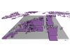
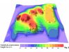
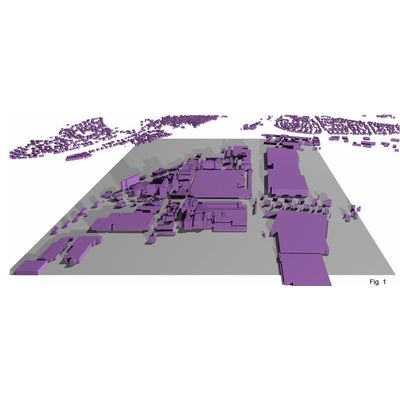
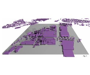
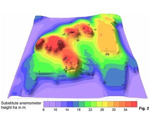
As a rule, this is an area h (x, y) which is dependent on the horizontal coordinates x and y. As an example, the possible substitute anemometer heights h (x, y) at which the mean wind speed corresponds to the transferred or modeled meteorological data are shown in Fig. 2 for an area shown in Fig. 1.
Points at which the height h (x, y) is calculated directly in the vertical layer above a building are discarded ("holes" in Fig. 2).
In a second step, the local wind direction and wind speed influenced by buildings is compared with the transferred or modeled wind direction and wind speed on the area h for 36 wind directions.
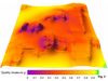
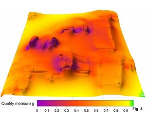
From this, the error sum for the 36 wind directions is calculated and normalized (smallest or largest value is set to 1 or 0). These two normalized error square sums represent the quality measures gd and gf for wind direction deviation and wind speed deviation.
The quality measure g, from which the optimal SAP is derived, is the product of gd and gf (see Fig. 3).
The optimum SAP in the investigation area is the position on the surface h (x, y) at which the quality measure g has its maximum (white triangle in Fig. 3).
As an undesirable side effect, different heights on the surface h (x, y) also result in different turbulence fields for the dispersion calculation.
As a result, the relevant parameters can be specified separately in the WinMISKAM interface for generating the turbulence fields.
Since this isolation is not provided for the dispersion calculation with AUSTAL when using the diagnostic flow model TALdia integrated in AUSTAL, the method presented can hereupon only be applied to a limited extent.
Contact person:
Dr.-Ing. Thomas Flassak