

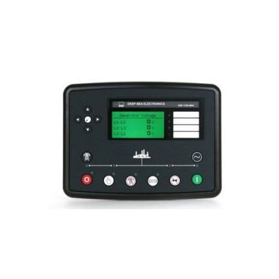
MKII - Model DSE7320 -Auto Mains Failure Control Module
OVERALL SIZE
245 mm x 184 mm x 51 mm (9.6" x 7.2" x 2.0")
PANEL CUTOUT SIZE
220 mm x 160 mm (8.7" x 6.3")
MAXIMUM PANEL THICKNESS
8.0 mm (0.3")
PRODUCT VARIANTS
7320-03 - 7320 MKII Auto Mains Failure Control Module
Comprehensive monitoring of the mains (utility) supply and auto changeover
4-line back-lit LCD text display
Five key menu navigation
Support for up to three remote display units
Configurable inputs (8)
Configurable analogue / digital inputs (6)
Configurable outputs (8)
Tier 4 CAN engine support.
Integral PLC editor
Manual fuel pump control
Power monitoring (kWh, kVAr, kvAh, kVArh), reverse power protection, kW overload protection.
Mains monitoring and automatic start and changeover to generator power in the event of a mains (utility) out of limits or failure.
Configurable CT positioning
Data logging facility
Customisable power up text and images
Support for 0-10 V & 4-20mA oil pressure senders
A genset controller and ATS in one compact housing
Provides comprehensive and clear indication of operation and parameters
Provides convenient and flexible navigation of parameters
Provides the option to mimic the main control module up to 1.2 km
Provides multiple installation options
Provides flexibility for multiple installation options
Provides multiple installation options
Ensures the control module can be used with the latest in modern electronic engine technology.
Ensures additional applications are easily integrated into the system
Allows the fuel tank to be filled to provide reassurance of system operation
Provides clear accurate power measurement information
Provides the reassurance of back up power being available in an emergency.
The CT can be placed in the Generator output to provide current readings and protection or alternatively placed in the main load output to provided generator and mains (utility) readings and protection.
Provides current and historical status information
Company logo can be uploaded to the start up splash screen
Provides support for a wide range of sensors and parameters
8 V to 35 V Continuous
5 V for up to 1 minute
CRANKING DROPOUTS
Able to survive 0 V for 100 mS, providing supply was at least 10 V before dropout and supply recovers to 5 V. This is achieved without the need for internal batteries. LEDs and backlight will not be maintained during cranking.
MAXIMUM OPERATING CURRENT
510 mA at 12 V, 240 mA at 24 V
MAXIMUM STANDBY CURRENT
330 mA at 12 V, 160 mA at 24 V
CHARGE FAIL/EXCITATION RANGE
0 V to 35 V
VOLTAGE RANGE
15 V to 415 V AC (Ph to N)
25 V to 719 V AC (Ph to Ph)
FREQUENCY RANGE
3.5 Hz to 75 Hz
+/- 0.5 V to 70 V
FREQUENCY RANGE
10,000 Hz (max)
ELECTRO-MAGNETIC COMPATIBILITY
BS EN 61000-6-2
EMC Generic Immunity Standard for the Industrial Environment.
BS EN 61000-6-4
EMC Generic Emission Standard for the Industrial Environment.
ELECTRICAL SAFETY
BS EN 60950
Safety of Information Technology Equipment, including Electrical Business Equipment.
TEMPERATURE
BS EN 60068-2-1
Ab/Ae Cold Test -30°C.
BS EN 60068-2-2
Bb/Be Dry Heat +70°C.
VIBRATION
BS EN 60068-2-6
Ten sweeps in each of three major axes.
5 Hz to 8 Hz @ +/-7.5 mm, 8 Hz to 500 Hz @ 2 gn.
HUMIDITY
BS EN 60068-2-30
Db Damp Heat Cyclic 20/55° C @ 95% RH 48 Hours.
BS EN 60068-2-78
Cab Damp Heat Static 40° C @ 93% RH 48 Hours.
SHOCK
BS EN 60068-2-27
Three shocks in each of three major axes 15 gn in 11 ms.
BS EN 60529
IP65 - Front of module when installed into the control panel with the supplied sealing gasket.