
- Home
- Companies
- Guangdong Pumbaaev Drive Technology ...
- Products
- Pumbaaev - Model PMC10A - Electric ...
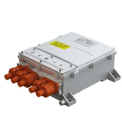
Pumbaaev - Model PMC10A -Electric Vehicle Motor Controller Unit (MCU)
The Motor Control Unit (MCU) is an electronic module between the battery and the motor that controls the speed and acceleration of an electric vehicle based on the input of the switch. The controller converts the direct current of the battery into alternating current, and adjusts the power output of the battery to drive the motor. The controller can also reverse the rotation of the motor and charge the battery in reverse during regenerative braking. The Motor controller of electric vehicles can be broadly divided into the following categories, depending on voltage, power and current:
Major functions of MCU
Motor Control Unit is the central control hub of electric vehicle motor, which performs many important functions to ensure smooth and efficient driving. Its main function is to convert the DC (direct current) supplied by the battery into the three-phase electric power (AC) that drives the motor.
In addition, the MCU monitors key parameters such as temperature, current and voltage to optimize motor performance and prevent potential failure. It can also accurately control the speed, torque and direction of the motor and the corresponding output power of the motor according to the input of the driver or the vehicle control system.
- The main functions of the motor control unit (MCU) are: Control motor torque and speed
- Start/Stop the motor
- Prevent electrical failure
- Provide overload protection
- Change the direction of motor rotation
- Regenerative brake
MCU is a typical hardware architecture
The following figure shows a typical hardware architecture diagram of a MCU. It is mainly composed of power supply, current detection circuit, inverter circuit (VSI) , CAN transceiver and MCU.
- Microcontroller MCU: the main control input of the microcontroller itself comes from a switch signal that the driver can control. The switch signal will determine how the duty cycle of the PWM pulse changes to obtain the required speed and torque. In order to realize the high efficiency and fast control, the microcontroller can implement the FOC control.
- VSI (Voltage Source Inverter) : the main function of VSI is to convert DC to AC via the position feedback of the motor. In general, VSI uses six igbts. However, in order to improve the current capability of the inverter, the parallel combination of igbts will also be used. Low-voltage motors (typically below 100V) use MOSFET (metal oxide semiconductor field effect transistor) , while high-voltage motors use GaN power switches and silicon carbide (SiC) insulated-gate bipolar transistor (IGBT) drivers.
- Current detection circuit: for Induction Motor Phase Current, a current sensor based on Houle effect is used. In general, two current sensors are used to sense the two-phase current, and the third-phase current is derived from these two sensors.
- Power: different levels of power are required to power microcontrollers, motor temperature sensors, and position sensors. In addition, because the microcontroller has built-in current sensors, power is required to provide these sensors with the appropriate bias voltage. To meet these requirements, the power part converts the battery`s DC voltage into different voltages as needed.
- Gate Driver: The Gate driver circuit amplifies the PWM pulse voltage level generated by the microcontroller to drive the IGBT.
- Can Transceiver: the function of CAN transceiver is to transmit and receive data on CAN bus. The communication between MCU and other modules on the vehicle is realized.
How the MCU works
The microcontroller MCU is responsible for executing complex control algorithms and managing the overall operation of the motor. It also provides an external communication interface (mainly CAN) that enables it to communicate with other ecus in the system and obtain control information from the VCU. The PWM signal generated by MCU is amplified by gate driver and used to control power switch IGBT. Inverter VSI can realize the conversion between DC and AC. Usually, six igbts with three half-bridges are used to realize this conversion, and the number of parallel connections is increased to meet the current requirements of the motor. Various detection and sampling circuits provide feedback of motor parameters, such as position, phase current, temperature, etc. , for accurate control.
There are many types of motor, such as BLDC/PMSM DC motor and AC motor. Therefore, the motor control algorithm used in electric vehicles will depend on the motor and the type of control (open-loop or closed-loop).
- Use SVPWM modulation algorithm to improve the energy efficiency ratio of the power system
- Configure high-efficiency CAN communication module to control the normal operation of the system
- Have liquid temperature control system and excellent waterproof and moisture-proof performance to extend the use time of the product and the vehicle
- Adopt torque vector control mode to realize energy recovery and utilization;
- Have perfect protection function to ensure the safe operation of the vehicle.
- Platform-based design to meet the different requirements of different vehicles, The localization rate exceeds 90%
- Light weight design,high power density, improve vehicle range
- Compact design,small size, flexible installation , save vehicle packaging space
- Modular design,flexible change of package according to the customer requirements
High performance: the controller has a high overload capacity at low speeds (usually more than twice the rated current), and a wide weak magnetic constant machine capacity at high speeds.
High torque: when the starting torque is large, the controller is required to output a larger current at low speed.
Large speed: In the higher speed range, the drive system needs a larger constant power area, therefore, the controller is required to have a strong weak magnetic capability.
High efficiency: The energy of new energy vehicles are valuable, and the efficiency of the drive system directly affects the range, so the high efficiency of the drive system is required to minimize the loss of the drive system.