

Renesas Electronics Corporation
- Home
- Companies
- Renesas Electronics Corporation
- Products
- Renesas - Model EK-RA6M4 - Evaluation ...
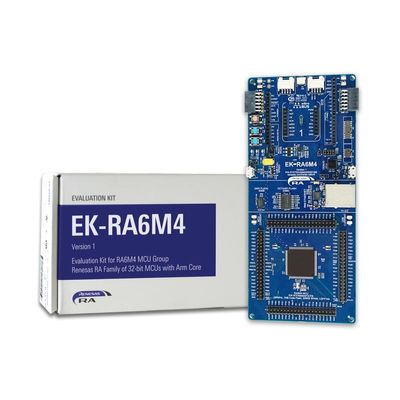
Renesas - Model EK-RA6M4 -Evaluation Kit for RA6M4 MCU Group
The EK-RA6M4 evaluation kit enables users to effortlessly evaluate the features of the RA6M4 MCU Group and develop embedded systems applications using the Flexible Software Package (FSP) and e2 studio IDE. Utilize rich on-board features along with your choice of popular ecosystem add-ons to bring your big ideas to life.
Most popular related searches
Running the Quick Start Example Project
- The EK-RA6M4 comes pre-programmed with a Quick Start example project (source code provided in the EK-RA6M4 Example Project Bundle (ZIP)).
- Power up the EK-RA6M4 board through the debug USB port (J10) using the micro USB device cable connected to a 5V power source. The white power LED will light up.
- The Quick Start example project will begin to execute blinking the blue user LED.
- Refer to the EK-RA6M4 – Quick Start Guide (PDF | English, ???) to explore additional functionality of the Quick Start example project.
- Modifying the Quick Start example project – Refer to the EK-RA6M4 Quick Start Guide for instructions on importing, modifying, and building the Quick Start example project
- Start with one of the many other example projects – Choose from many example projects provided in the EK-RA6M4 Example Project Bundle to learn about different peripherals of the RA6M4 MCU Group. These example projects can serve as excellent starting points for you to develop your custom applications.
- Start by building a functional prototype – Utilize the EK-RA6M4 board with your choice of hundreds of popular ecosystem add-ons.
- Build custom hardware – Develop custom hardware by referring to the design and manufacturing information provided in the EK-RA6M4 v1 - Design Package (ZIP | English, ???).
- Ecosystem & System Control Access
- USB Full Speed host and device
- Multiple 5V input sources
- USB (Debug, Full Speed)
- External power supply
- SEGGER J-LinkTM on-board programmer and debugger
- Debug modes
- Debug On-board (SWD) – via J-Link
- Debug Out (SWD) – via J-Link
- Debug In (ETM, SWD & JTAG) – via J-Link, Arm® Keil® ULINKTM, IAR I-jetTM, Renesas E2/E2 Lite, etc.
- User LEDs and buttons
- Three user LEDs (red, blue, green)
- Power LED (white) indicating availability of regulated power
- Debug LED (yellow) indicating the debug connection
- Two user buttons
- One reset button
- Five most popular ecosystem expansions
- MikroElektronikaTM mikroBUS connector
- SparkFun® Qwiic® connector
- Two SeeedGrove® system (I2C and Analog) connectors
- Two Digilent PmodTM (SPI and UART) connectors
- ArduinoTM (Uno R3) connector
- MCU boot configuration jumper
- Special Feature Access
- Ethernet (RMII and PHY)
- 64MB External Octo-SPI Flash
- 32MB External Quad-SPI Flash
- MCU Native Pin Access
- R7FA6M4AF3CFB MCU
- 200MHz, Arm Cortex®-M33 core
- 1MB Code Flash, 256kB SRAM
- 144 pins, LQFP package
- Native pin access through 4x 40-pin male headers
- MCU and USB current measurement points
- Kit Contents: EK-RA6M4 board, Micro USB device cable (type-A male to micro-B male), Micro USB host cable (type-A male to micro-B male), Ethernet patch cable