

- Home
- Companies
- GP Green Energy Systems Pvt. Ltd. (GP ...
- Products
- GP - Gasifier Plant
GP - Gasifier Plant
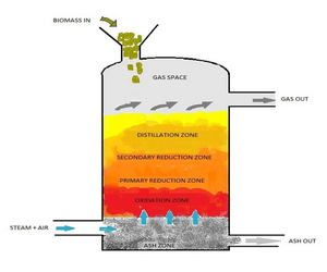
The solid biomass fuel having moisture content not exceeding 20% and 25mm in size is fed from the top of the Gasifier, while air and steam are fed from the bottom.The air and steam move upward against the downward movement of the biomass fuel, generating producer gas . This process of gas generation is the principle behind Updraft gasification.While the plant is under normal operation, following zones are believed to exist in the gasifier from bottom to top, as shown in the cross sectional view.
Ash Zone: A flow of heat takes place from hot ash to the air and water vapour entering the system and thus the hot process air enters the oxidation zone and the cooled ash leaves the system at the bottom to the water seal, generally maintained at about 600 mm wg.
Oxidation Zone : It is a narrow zone having the highest temperature(9500C–11000C) in the Gasifier due to the exothermic reaction:
C + O2 = CO2 + Heat
Primary Reduction Zone : The heat released by the oxidation zone below is cooled down by the endothermic reactions in this zone with the formation of CO, H2 and CO2 by the interaction of C present in the fuel with O2 and H2O present in the process air:
- C + CO2 = 2CO ~ Heat
- C + H2O = CO + H2 ~ Heat
- C + 2H2O = CO2 + 2H2 ~ Heat
Secondary Reduction Zone : It reduces further the temperature of the gas coming out of the zone below due to endothermic reactions with the production of CO by the interaction of C with CO2 and simultaneous water gas reaction as follows:
C + CO2 = 2CO ~ Heat
CO + H2O = CO2 + H2 ~ Heat
Distillation zone : The heat of the upward moving gas from the secondary reduction zone helps the distillation of the volatile matters present in the fuel with the evolution of highly volatile hydrocarbons which combine with the gas to enrich it in its calorific value and the temperature of the gas goes down further .
The interior of the reactor is designed to provide adequate space and time for the above thermo-chemical reactions to enrich the gas and increase its calorific value.
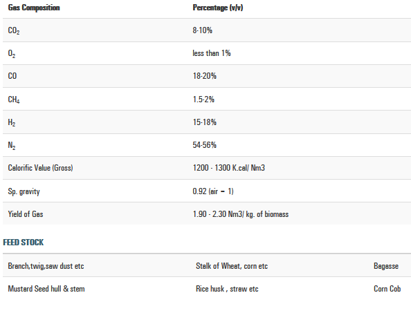
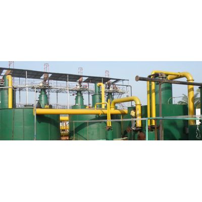
In GP Gasifiers, solid biomass, a carbonaceous fuel is burnt under controlled air and water in the Gasifier reactor to produce a combustible (carbon–monoxide based) gas, generally known as producer gas. This gas having calorific value of 1200–1350 Kcal/Nm3 can be used for generation of electrical power and/or thermal energy. However, before this gas is used, it is important to clean and cool it as it contains tar and other impurities, for which an elaborate gas cleaning and cooling system is provided. The capacity of such plants ranges from 10kW to 1MW. Systems are designed for cogeneration in the industries based on specific requirement of the clients. Higher capacities can be achieved by incorporating multiple systems.
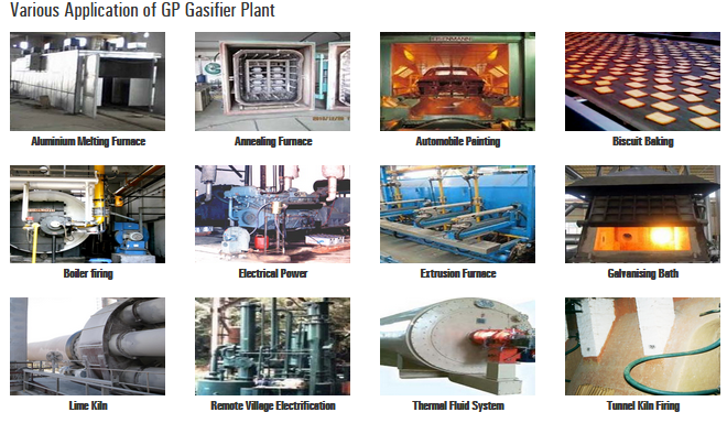
Thermal Energy:
Since producer gas is combustible in nature, the same can be fired with the help of a suitably designed burner. Boilers, furnaces, ovens etc can then be gas fired to replace furnace oil, LPG, HSD, CNG, coal or any other costly fossil fuels. In this case, there will be no ash/fly ash or particulate in the exhaust gas.
Again, temperature up to 1000 0 C can be achieved by burning the above gas. Hence, process heat for industrial applications namely, heating of water, air, fluid etc. is obtained from producer gas.
Electrical Power :
GP Biomass Gasifier Plant is highly suitable as a decentralized power station– both for captive use in the industries as well as for rural electrification, where transmission of power through grid line is very expensive and electrical load growth is minimal.
For generation of electrical power with producer gas, two types of engines can be used : -
Dual Fuel Engine: A dual fuel engine is basically a diesel engine with conversion kit to run the engine with diesel and any suitable gas having certain calorific value including producer gas. This works on the diesel cycle. Producer gas is added to the air, which is introduced to the engine before introducing it into the turbocharger. This mixture of air and gas is compressed in the cylinder just as air is compressed in normal CI engine. After compression, the diesel is injected through a conventional fuel system. This diesel oil ignites first as pilot fuel and the heat released by its combustion leads to the combustion of the gas air mixture. In the process, consumption of diesel can be reduced to the extent of 65%-75%. Existing engine may also be retrofitted for dual-fuel operation.
Spark Ignition Engine : The producer gas is the sole fuel in the Spark Ignition( SI) engine. A gas carburetor or mixer is used to prepare the air- gas mixture. The mixture is sucked into the engine during the suction stroke, compressed and then ignited by a spark from a spark plug in the cylinder head.
GP Systems have the following unique features:-
- It is a continuous operating system which can run on 24×7 basis.
- It is a multi fuel system and can accept any biomass in the same plant.
- Fuel consumption can be controlled as per actual requirement.
- The plant is sturdy in construction having adequate safety measures.
- GP Energy is approved by the Ministry of New & Renewable Energy, New Delhi and its systems attract cash subsidy and income tax benefit from the government. It also qualifies for carbon credit having scope for huge revenue inflow.