

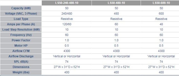
LBD - Model LS50 -Stationary Load Banks
The LS50 Stationary Load Bank offers the most robust, high-capacity, outdoor design in the industry. LBD is setting the standard with intelligent operator controls, safety indication layouts, adjustable load step resolution, and ease of installation. The LS50 is the perfect solution for regularly scheduled testing and commissioning of mission-critical standby emergency power systems.
- Outdoor Weatherproof Construction
- Rated for continuous duty with no cool-down period
- Highest Capacity in the smallest installed footprint
- Branch circuit fusing virtually eliminates catastrophic failure
- Slide Out Resistor Case Assemblies
- Intelligent Safety Circuits, Indicators, and Operator Controls
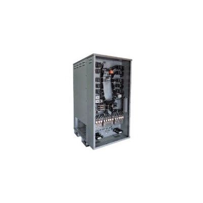
The LS50 is constructed of galvanized steel with the highest quality durable powder-coat paint finish, and external stainless steel fasteners. All power, motor, and control connections are provided in a sealed thermostatically controlled heated compartment to limit any harmful effects of moisture and condensation.
Remote Indication and Alarm
Contact closure [form-c-type normally open and normally closed] provides user interface to your building management system for indication, detection, and alarm of “Air-Flow Failure,” “Over-Temperature”, and “Load Dump”.
PowerDyne™ | When Quality Matters
PowerDyne™ Resistors are the most rugged in the industry. The non-corrosive resistance alloy can fully handle the effects of an outdoor installation. They are completely supported across their entire length within the air stream by stainless steel support rods which are insulated with heavy-duty, high-temperature ceramic insulators. Change in resistance is minimized by maintaining conservative resistor designs.
Control Power
External 120 Volt AC, 1-phase, 60 Hertz power required for control circuit operation. When 120 VAC control power is not readily available, units can be provided with a control power transformer.
Operator Protection | When Safety Matters
The LS50 comes equipped with an Emergency-Stop push button allowing the operator to take the unit off-line should a critical hard-stop condition occur. Branch circuit fuse protection provides short-circuit fault protection of all load steps eliminating the potential for catastrophic failure. Blower On, Motor Overload, Air-Flow Failure, and Over-temperature circuits disable all load steps during a fault condition with operator visual indicators. Dual Voltage units feature a Wrong Voltage Applied protection circuit which prevents the application of 480 VAC with the Load Voltage Selector switch in the 240 VAC position. The Load Dump circuit provides the operator visual indication if all load steps have been removed.
Operator Controls
- Emergency Stop (E-Stop)
- Illuminated Main Power On/Off switch
- Illuminated Blower Start/Stop Switch
- Load Voltage Selector switch (dual voltage units)
- Master Load On/Off switch
- Individual Load Step Switches
- Fault condition smart indicators provide operator display and load disconnect during Air-Flow Failure, Overtemperature, Motor Overload, Load Dump, and Wrong Voltage Applied
Cooling System
- Integrally mounted blower motor with high-performance, direct-driven fan blade delivers the required airflow volume (CFM) for cooling resistor load elements
- Blower motors can be wired to operate internally off the main input load bus or from an external 3-phase power source
- Motor circuits are short-circuit protected by current-limiting fuses and thermally protected by overload relays
Automatic Load Dump
This circuit provides user interface provisions to the generator controls, automatic transfer switch, or building management system, to disconnect and disable all load steps from a normally closed (NC) set of auxiliary contacts. In the event of an actual power failure, all load bank load is removed from the source under test.
This circuit provides user interface provisions to the generator controls, automatic transfer switch, or building management system, to disconnect and disable all load steps from a normally closed (NC) set of auxiliary contacts. In the event of an actual power failure, all load bank load is removed from the source under test.
The Automatic Load Level Controller [ A ] will add/subtract load bank load in response to dynamic power fluctuations of the connected building load. It utilizes the load bank as a “supplemental load” for maintaining a minimum load on the power source. Customer “transfer of control” contact closure initiates the load bank and time delay load application circuit. A separately supplied current transformer provides the necessary feedback signal for sensing building load.
Integral Control Power Transformer [ T ] which delivers the necessary 120 Volt AC, 1-phase, 60 Hertz power required for control circuit operation. Control power transformer is wired to blower motor circuit and is primary and secondary fuse protected.
Local Operator Control Panel [ L ] - The Remote Operator Control Panel is provided as a Local Control Panel which is mounted and wired to the Load Bank Enclosure.
Digital Power Meter [ M ]: Fully equipped, 3-phase Digital Metering System that measures a standard range of 16 load parameters. Includes RS485 (Modbus protocol) for remote reading - compatible with PC, PLC, and data loggers. See additional details at: http://www.multitek-ltd.com/HTMs/M800/M850.htm.
Horizontal Airflow Discharge [ LB ] units are available up to 500kW.