

- Home
- Companies
- Beijing Bona Electrical Limited by ...
- Products
- Model DTZY88 - Three-Phase Four-Wire ...
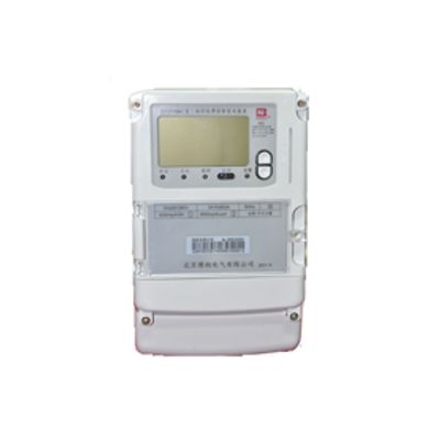
Model DTZY88 -Three-Phase Four-Wire Cost-Control Intelligent Meter
Model DTZY88 three-phase four-wire cost-control intelligent meter (remote/in-built switch) is composed of measuring unit, data-processing unit and communication, and has functions of electric energy metering, data processing, real-time monitoring, automatic control, information interaction and etc. The large scale integration technology and SMT manufacturing process, as well as the selected international brand key component with long life, highly improve the reliability and service life of the product. With large screen LCD displaying data, the product has high accuracy and reliability.
II. Specification
2.1 Voltage specifications: 3×57.7/100V,3×100V,3×220/380V.
2.2 Current specifications: the reference currents (In) are 0.3A, 1.5A, 5A, 10A, 20A. The maximum current is not less than 4 times of the reference current.
2.3 Reference frequency: 50Hz.
III. Electrical Performance Index
3.1 Environmental conditions
3.1.1 Reference temperature and reference humidity
The reference temperature is 23℃ and the reference humidity ranges from 40% to 60%.
3.1.2 Temperature and humidity
Temperature range:
|
Installation way
|
Indoor type
|
Outdoor type
|
|
Operating range
|
10℃~45℃
|
25℃~60℃
|
|
Limit range of operation
|
25℃~60℃
|
40℃~70℃
|
|
Limit range for storage and transportation
|
25℃~70℃
|
40℃~70℃
|
Relative humidity:
|
Annual mean
|
<75%
|
|
30 days (These days distribute in the year in a natural way.)
|
95%
|
|
Occasionally appear in other days
|
85%
|
3.1.3 Atmospheric pressure
63.0kPa~106.0 kPa (No more than altitude 4000m).
3.2 Voltage range table.
|
Operation range
|
0.8Un~1.2Un
|
|
Limit range of operation
|
0.0Un~1.2Un
|
3.3 Error: Active class 0.5S conforms to the provisions of IEC 62053-22; Reactive class 2 conforms to the provisions of IEC 62053-23. And the error data is within 60% of the factory tolerance limit.
3.4 Within the rated voltage and the rated frequency and under the condition of cos=1.0, after the load current rising up to 0.001In, the meter can output metering pulse, and the indicator light representing the output of electric energy will flash.
3.5 Creeping
When there is no current in the current loop and 115% Un are applied to the voltage circuit, the meter can output no more than 1 pulse within the 10-fold time of generating a pulse under the starting current.
3.6 Demand indication error
Within the rated voltage and the rated frequency and under the condition of cos=1.0, if I=0.1In~Imax, the demand indication error (%) will be not more than the stipulated level of accuracy values.
3.7 Clock accuracy
At the reference temperature (23℃) and within the range of operating voltage, the accuracy of the internal clock will be better than 0.5s/d.
Within the range of operating temperature (25℃~+60℃), under the condition of AC power supply and DC battery supply, the accuracy of the internal clock will be not more than ≤1.0 s/d.
IV. Functions
4.1 Metering of power
4.1.1 Metering of positive active power and reverse active power, and metering of four-quadrant reactive power. Combination portfolio of active power and combination portfolio of reactive power can be set accordingly.
4.1.2 In addition to separate recording and displaying, four-quadrant reactive power can also be programmed by software to realize the computing, recording and displaying of combination of reactive power I and combination of reactive power II. (Note: Circularly displaying of combination of reactive power I and combination of reactive power II, however, the reactive amount of four quadrants can be displayed and collected.)
4.1.3 Time-sharing metering can separately accumulate and store the active power and reactive power in total and those in sharp, peak, flat and valley period.
4.1.4 Metering of phase-separation active power.
4.1.5 Storage of power data for 12 settlement days. The settlement time can be set on the hour any day in each month.
4.1.6 Setting of meter parameters according to need; the power parameter cannot be set at a bottom-end value unless be reset; only when the hardware programming key is pressed can resetting be allowed.
4.2 Demand metering
4.2.1 Metering of bidirectional maximum demand and time-segmented maximum demand as well as the date and time of appearance, and storage of time-tagged data.
4.2.2 The maximum demand value can be manually (or by using meter reader) cleared. Manual clearing of demand value requires pressing of the reset button and a password protection in case of operation by unauthorized person.
4.2.3 A slip way is used for the maximum demand values. The demand period and slip time can be set. The factory default of demand period is 15 minutes and slip time is 1 minute.
4.2.4 Under situations such as energizing of voltage line, time conversion, clearing, clock adjustment and etc, the power meter will measure the demand according to demand cycle from the beginning of the present time. When the first demand cycle is completed, the power meter starts to measure the maximum demand according to the slip difference. In an incomplete demand period, the power meter will not record the maximum demand.
4.2.5 Storage of the maximum demand data for 12 settlement days.
4.3 Display Function
4.3.1 The displayed content of meter includes the main data and the auxiliary code and characters;
4.3.2 There are two display ways: automatic circularly display and key-press display. The display items can be set according to requirements. The LCD backlight mode will be started for the key-press display. The circular period can be set in the range from 5 to 20 seconds, and the default value is 5 seconds;
4.3.3 Abnormal reminder. When the meter is running abnormally (loss of voltage, serious imbalance of current, open phase, reverse phase sequence, etc.), the display will stay on the code and simultaneously start light alarm. The error codes include the following failures: internal program errors, clock errors, memory faults or damage.
4.4 Function of clock, time period and rate
4.4.1 The inbuilt hardware clock circuit with temperature compensation has functions of calendar, timing and automatic switching of leap year. The output frequency of the internal clock terminal is 1Hz.
4.4.2 Two sets of rate period that can be automatically switched through pre-setting of time period. Two time zones can be set annually for either rate period, and 8 time periods can be set within 24 hours, with the minimum time interval not less than 15 minutes. The interval between time periods is longer than the value of the demand period set in the table. The time period can set across zero o’ clock.
4.5 Time calibrating
4.5.1 The time of meter can be calibrated through RS485, infrared and other communication interface. Except for broadcasting time calibration, only under the programming state can time calibration be realized.
4.5.2 Broadcasting time calibration does not require the programming key or communication password, and is allowed only once a day. The acceptable range of broadcasting time calibration cannot be more than 5 minutes. Broadcasting time calibration of meter should not be within 5 minutes before or after the performance of freezing or settlement data transferring; when the calibration time is more than 5 minutes, the time of meter can only be calibrated on site.
4.6 Measurement and monitor
The meter can measure, record and display the current operating parameters such as the voltage, the current, the power, the power factor and etc of total and of each phase. The measurement error (fiducial error) will not exceed by ±1%.
The provided threshold-crossing monitoring function can set limits for parameters such as line (phase) voltage, current, power factor and etc, and monitor them. When a parameter exceeds or falls below the set limit, it will be recorded in the form of event log. The recording format will be in line with the requirement of DL / T 645-2007 and the filings.
4.7 Event Log
4.7.1 Recording of the total number of programming, and the time, the operator code, and the data identification of programming item of last 10 programmings.
4.7.2 Recording of the total number of demand clearing, and the time and the operator code of last 10 demand-clearing operations.
4.7.3 Recording of the total number of time calibration (without broadcasting time calibration), and the time and the operator code of last 10 time calibrations.
4.7.4 Recording of the total number of voltage loss of each phase, and the occurrence time, the end time as well as the corresponding electric power data of last 10 voltage losses.
4.7.5 Recording of the total number of phase failure of each phase, and the occurrence time, the end time as well as the corresponding electrical power data of last 10 phase failures.
4.7.6 Recording of the total number of current loss of each phase, and the occurrence time, the end time as well as the corresponding electrical power data of last 10 current losses.
4.7.7 Recording of the occurrence time, the end time as well as the corresponding electrical power data of last 10 current imbalances.
4.7.8 Recording of the total number of reverse phase sequence of voltage (current), and the occurrence time, the end time as well as the corresponding electric power data of last 10 reverse phase sequences.
4.7.9 Recording of the total number of meter-cover opening event, and the occurrence time and end time of last 10 meter-cover opening events.
4.7.10 Recording of the total number of terminal-cover opening event, and the occurrence time and the end time of last 10 terminal-cover opening events.
4.7.11 Permanent recording of the occurrence time and the electric power data of meter clearing event.
4.7.12 Recording of the total number and total duration of the overload of each phase, and the duration of last 10 overloads.
4.7.13 Recording of the total number of power down, and the occurrence time and the end time of last 10 power-down events.
4.7.14 Recording of the total number of complete loss of voltage, and the occurrence time, the end time and the corresponding current value of last 10 complete losses of voltage.
4.7.15 Reading of the total number and/or the total cumulative time of each event log.
4.8 Freezing
4.8.1 Freezing at fixed time: freezing of the electric power data as per specified time and time interval. Each frozen data will be kept for 12 times.
4.8.2 Instantaneous freezing: Freezing of all current data of electric power, calendar and time as well as important measurement data under abnormal condition. Instantaneous frozen data of the last three times will be kept.
4.8.3 Agreed freezing: Freezing of electric power data as well as other important data at an agreed time when there is conversion from old rate/time to new one, or when electric power company believes there are special requirements.
4.8.4 Day freezing: Storage of electric power daily data at zero o’ clock for 2 months.
4.8.5 The content of freezing and the data identifiers are in line with the requirements of DL/T 645-2007 and filings.
4.9 Load Record
4.9.1 Content of load record is random combination of six types of data items defined in DL/T 645-2007: "voltage, current, and frequency", "active power and reactive power", "power factor", "total active electric power and total reactive electric power", " the total reactive electric power of four quadrants", and "current demand".
4.9.2 Interval time of load record can be set within the range from 1 minute to 60 minutes. The time interval for each type of load record may be the same or different.
4.9.3 Storage capacity of load record data for not less than 40 days can be ensured on condition that with time interval of 1 minute, the data of total active electric power, total positive and negative reactive electric power, total reactive electric power of four-quadrant, active combination, reactive combination I, and reactive combination II are recorded.
4.10 Meter reading of power failure
When there is power failure, the meter can be woken up by pressing button or non-contact ways so data of electric power and etc can be read.
4.11 Data storage function
4.11.1 Storage of the total bi-directional electric power data and the electric power data of each rate for the last 12 settlement days. The time-dividing point of data transferring is at 24 o’ clock on the last day in a month (at 0 o’ clock on the first day in a month), or on the hour from the first day to the 28th day in each month.
4.11.2 Storage of the bi-directional maximum demand, and the maximum demand of each rate as well as the respective data of occurrence date and time for 12 settlement days. The time-dividing point of data transferring is at 24 o’ clock on the last day in a month (at 0 o’ clock on the first day in a month), or on the hour from the first day to the 28th day in each month. At the same time of data transferring on the end day of a month, the maximum demand of that month will automatically reset to zero. Neither does the maximum demand transfer nor does the maximum demand reset to zero at other times.
4.11.3 If there is power loss for the meter, all the data related to settlement will be kept for not less than 10 years, and the other data for not less than three years.
4.12 Data clearing
Data clearing of meter must be permanently recorded as an event; all clearing instructions include safety measures, such as hardware programming switch, operation password or seal management, data saving before clearing and etc, to prevent operations by unauthorized person.
4.13 Communication Requirement
4.13.1 The meter has one infrared communication interface, one RS485 communication interface, and one carrier communication interface. The infrared communication interface, the RS485 communication interface, and the carrier communication interface are physically independent. Damage of one communication channel does not affect the other channels. In addition, the communication interface should be electrically isolated from the internal circuit of power meter to effectively protection the circuit.
4.13.2 The electrical and mechanical performance of the infrared communication interface, the RS485 communication interface and the carrier communication interface should meet the requirements item 4.8 in the Functional Specification of Intelligent Meter of State-Grid Company.
4.13.3 The technical requirements of the signal band, the maximum output signal level, the interference level beyond the used band and etc of the carrier communication module meet item 4.6.1 in DL / T 698.35. Measurement data and parameters under non measurement and non-communication status will not be affected and changed.
4.13.4 The RS485, infrared, carrier and other communication of the meter are in line with the DL/T 645-2007 Agreement and its filing documents. The network protocol of carrier communication meets the requirement of 698.42.
4.13.5 Supporting of modification of time table of rate as well as the electricity tariff rate scheme through the infrared interface and the RS485 communication interface with safety measures, such as setting of hardware programming switch and operation password, seal management, data saving before clearing and etc, to prevent operation by unauthorized person.
4.13.6 Supporting of modification of time table of rate as well as the electricity tariff scheme through authorized CPU card and radio frequency card.
4.14 Pulse output
The meter has the function of outputting LED pulse and power pulse in proportion to the measured electric power.
The characteristics of the output device for optical test meet the requirements of GB/T 17215.211-2006. The characteristics of the output device for electrical test are in line with the requirements of GB/T 15284-2002.
4.15 Voltage loss and phase failure
The meter will record and send prompt message for the voltage loss and phase failure of any phase.
The voltage-loss function of the meter meets the technical requirement of DL/T 566-1999.
4.16 Cost control function
The cost control function of the meter is remote control, which is realized via remote electricity vending system and virtual media such as public network and etc.
4.16.1 Control Function
When the remaining amount of money of the meter is less than or equal to the set amount, the power meter will give alarms in the form of sound, light or other means to alert the user; Real time recording of overdrawn amount -- when the overdrawn amount is less than the threshold amount set in advance, the power meter will issue power-off signal to control the load switch to interrupt the power supply; After receiving effective renewal information, the power meter will deduct the overdrawn amount first, and only when the remaining amount is more than the set value (the default is zero), can the power meter be switched on through remote or local way to manually restore the power supply by user.
4.16.2 Memory function
When the power is cut off in the supply line, the remaining amount and other information needs to be protected will not get lost.
4.16.3 Superposition
The deposit amount of electricity can be accurately superimposed with the remaining amount of electricity of the meter.
4.16.4 Writing back
Upon completion of prepayment of electricity, the meter will write the information of the remaining amount, the electricity parameter and etc back to the solid medium or send them back to the power vending system through virtual media according to the cost control way.
4.16.5 Discrimination
Use of non-specified media to input power purchase amount will not be accepted by the power meter.
4.16.6 Parameter setting
The electricity parameters in the power meter can be set by virtual media on the precondition of safety.
4.16.7 Safety Certification
Operations of parameter setting, deposit of electricity, back writing of information and remote control command towards the power meter through virtual media have passed strict safety certification of ESAM module, so as to ensure the safety and reliability of data transmission.
The SM1 cryptographic algorithm is adopted in the encryption algorithm of ESAM module.
4.17 Tiered pricing for electricity
There are two charge modes of tiered pricing for electricity. The other set of billing can be enabled at the set point of time.
V. Meter storage:
The power meter must be transported and stored under the original packing condition. It should be installed indoors as much as possible; otherwise, the special meter box should be adopted to protect the meter for outdoor installation. The corrosive gases may not be existed in the storage environment and the storage height shall not exceed five layers.