

Project Engineering
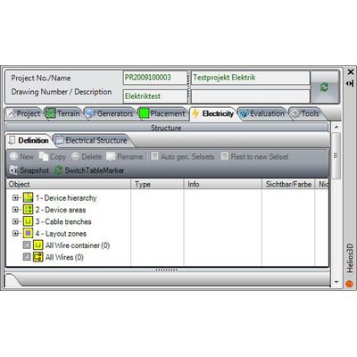
The Device Hierarchy (Picture 17) describes the basic electrical structure of the electrical system.
The Device Areas contain the physical, electrical devices (inverter, transformer, ...) with the assigned amount and specific type.
The Cable Trenches describe the distribution of the cable trenches and the assignment to the fields.
The Layout Zones contain the selection sets which define the assignment of the specific device hierarchies.
These structures and this multiple possibilities deliver the degree of flexibility, that is necessary for a total individual electrical layout.
After the basic structure is defined, the logical devices get their final technical specifications by assigning specific electrical devices with their parameters (Number of connections, max voltage, max. current,..)
These components can be selected from an article database. At the cable symbol for each connection several cable types with different cross-sections can be assigned (Picture 18). The default cable, that is used for the initial layout is on top of the list. In a future version of HELIOS 3D, it will be possible to define the maximum allowed power dissipation, and HELIOS 3D then can check for cable lengths, where this parameter is exceeded. As a consequence HELIOS 3D will select the specific cable, that keeps losses within the specs.
A special tool comes with the string configurator (Picture 19). With its separate dialog box, it is possible to describe not only the physical connection of the single modules on a rack, but also the assignment of the strings to the inputs of the selected combiner box/string inverter.
With the two modes to define strings “Quick and easy” (rack oriented mode) or “Expert” (fully individual string design) any requirement for flexibility or speed can be covered. Any number of definitions can be defined and saved. In Expert mode the string definition need not match the horizontal multiple of modules on the rack, but can have any length necessary to meet the technical requirements.
The device areas (Picture 21) have two purposes. They are a connecting element for the definition of trench structures and they contain the type and amount of electrical devices that will be placed by HELIOS 3D at this specific area when it assigns the string structure to the physical layout. The total amount of devices that need to be placed to cover the available power output is distributed between these device areas.
The layout zones are a special kind of selection sets, (Picture 20) created to individually assign the string definitions. HELIOS 3D can them automatically or the user can make any selection he needs. They can be edited, split and connected to contain the individual racks, that should have a special string definition. The sets have a color assigned to differentiate between them.