Vertogen Ltd
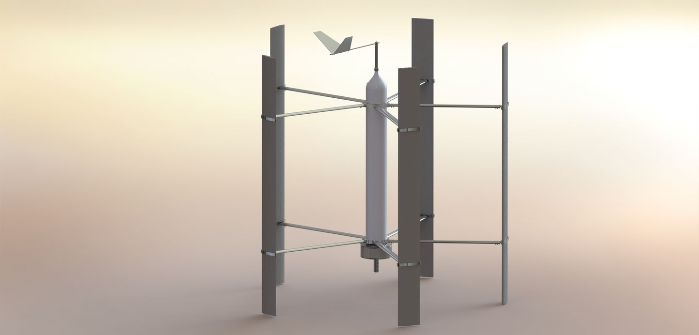
Vertogen Ltd manufacturer of Variable Pitch Vertical Axis Wind Turbine. After 10 years of investment and development by an innovative UK Company we are now offering an opportunity for partners to join us in the final stages to refine, build and roll out on global basis. A design that will impact and reach across the globe to make a true difference to All and the Environment. https://youtu.be/wqQWg9rvTak
Company details
Find locations served, office locations
- Business Type:
- Manufacturer
- Industry Type:
- Wind Energy
- Market Focus:
- Globally (various continents)
- Year Founded:
- 2008
About us
A project with this Potential for Global requirement will need significant Investment, Foresight, Infrastructure and Management.
We are seeking Partners, Investors or Owners to take this and change the design of VAWT designs forever and make Clean Energy accessible for all.
Intellectual Property. Potential IP Licencing revenue is huge and significant protection needs to be in place so we require a large Company to implement this.
The technology behind our VAWT is the subject of pending UK patent application GB1710753.3. This application is currently undergoing accelerated completion as part of the UKIPO's Green Channel programme. We are hopeful that the application will be successful soon.
A History of Wind Turbines
Wind Power’s Beginnings
(1000 B.C. – 1300 A.D.)
The history of wind power shows a general evolution from the use of simple, light devices driven by aerodynamic drag wind power forces; to heavy, material-intensive drag devices; to the increased use of light, material-efficient aerodynamic lift devices in the modern era. But it shouldn’t be imagined that aerodynamic lift (the force that makes airplanes fly) is a modern concept that was unknown to the ancients.
The earliest known use of wind power, of course, is the sail boat, and this technology had an important impact on the later development of sail-type windmills. Ancient sailors understood lift and used it every day, even though they didn’t have the physics to explain how or why it worked.
The first windmills were developed to automate the tasks of grain-grinding and water-pumping and the earliest-known design is the vertical axis system developed in Persia about 500-900 A.D. The first use was apparently water pumping, but the exact method of water transport is not known because no drawings or designs — only verbal accounts — are available. The first known documented design is also of a Persian windmill, this one with vertical sails made of bundles of reeds or wood which were attached to the central vertical shaft by horizontal struts.
Grain grinding was the first documented wind mill application and was very straightforward. The grinding stone was affixed to the same vertical shaft. The mill machinery was commonly enclosed in a building, which also featured a wall or shield to block the incoming wind from slowing the side of the drag-type rotor that advanced toward the wind.wind power
Vertical-axis windmills were also used in China, which is often claimed as their birthplace. While the belief that the windmill was invented in China more than 2000 years ago is widespread and may be accurate, the earliest actual documentation of a Chinese windmill was in 1219 A.D. by the Chinese statesman Yehlu Chhu-Tshai.
Here also, the primary applications were apparently grain grinding and water pumping.
One of the most scenic and successful applications of windpower (and one that still exists), is the extensive use of water pumping machines on the island of Crete. Here, literally hundreds of sail-rotor windmills pump water for crops and livestock.
Windmills in the Western World
(1300 – 1875 A.D.)
The first windmills to appear in western Europe were of the horizontal-axis configuration (HAWT).
The reason for the sudden evolution from the vertical-axis Persian design approach is unknown, but the fact that European water wheels also had a horizontal-axis configuration — and apparently served as the technological model for the early windmills — may provide part of the answer. Another reason may have been the higher structural efficiency of drag-type horizontal machines over drag-type vertical machines, which (remember) lose up to half of their rotor collection area due to shielding requirements. The first illustrations (1270 A.D.) show a four- bladed mill mounted on a central post (thus, a “postmill”) which was already fairly technologically advanced relative to the Persian mills. These mills used wooden cog-and-ring gears to translate the motion of the horizontal shaft to vertical movement to turn a grindstone. wind power This gear was apparently adapted for use on postmills from the horizontal-axis water wheel developed by Vitruvius.
As early as 1390, the Dutch set out to refine the tower mill design, which had appeared somewhat earlier along the Mediterranean Sea.
The Dutch essentially affixed the standard post mill to the top of a multi-story tower, with separate floors devoted to grinding grain, removing chaff, storing grain, and (on the bottom) living quarters for the windsmith and his family. Both the post mill and the later tower mill design had to be oriented into the wind manually, by pushing a large lever at the back of the mill. Optimizing windmill energy and power output and protecting the mill from damage by furling the rotor sails during storms were among the windsmith’s primary jobs.
A primary improvement of the European mills was their designer’s use of sails that generated aerodynamic lift(see Figure 4 at the left). This feature provided improved rotor efficiency compared with the Persian mills by allowing an increase in rotor speed, which also allowed for superior grinding and pumping action.
The process of perfecting the windmill sail, making incremental improvements in efficiency, took 500 years. By the time the process was completed, windmill sails had all the major features recognized by modern designers as being crucial to the performance of modern wind turbine blades, including 1) camber along the leading edge, 2) placement of the blade spar at the quarter chord position (25% of the way back from the leading edge toward the trailing edge), 3) center of gravity at the same 1/4 chord position, and 4) nonlinear twist of the blade from root to tip (Drees, 1977).
wind powerSome models also featured aerodynamic brakes, spoilers, and flaps. The machine shown in Figure 4 (which was operating with two of its buddies pumping water about one meter up from one irrigation pond to another in the Netherlands in 1994) features leading edge airfoil sections.
These mills were the “electrical motor” of pre-industrial Europe. Applications were diverse, ranging from the common waterwell, irrigation, or drainage pumping using a scoop wheel (single or tandem), grain-grinding (again, using single or multiple stones), saw-milling of timber, and the processing of other commodities such as spices, cocoa, paints and dyes, and tobacco.
While continuing well into the 19th century, the use of large tower mills declined with the increased use of steam engines. The next spurt of wind power development occurred many thousands of miles to the west.
For hundreds of years, the most important application of windmills at the subsistence level has been mechanical water pumping using relatively small systems with rotor diameters of one to several meters. These systems were perfected in the United States during the19th century, beginning with the Halladay windmill in 1854, and continuing to the Aermotor and Dempster designs, which are still in use today.
The first mills had four paddle-like wooden blades. They were followed by mills with thin wooden slats nailed to wooden rims. wind power
Most of these mills had tails to orient them into the wind, but some were weather-vaning mills that operated downwind of the tower. Speed control of some models was provided by hinging sections of blades, so that they would fold back like an umbrella in high winds, an action which reduced the rotor capture area to reduce thrust. The most important refinement of the American fan-type windmill was the development of steel blades in 1870 (Figure 5). Steel blades could be made lighter and worked into more efficient shapes. They worked so well, in fact, that their high speed required a reduction (slow-down) gear to turn the standard reciprocal pumps at the required speed.
Between 1850 and 1970, over six million mostly small (1 horsepower or less) mechanical output wind machines were installed in the U.S. alone. The primary use was water-pumping and the main applications were stock watering and farm home water needs. Very large windmills, with rotors up to 18 meters in diameter, were used to pump water for the steam railroad trains that provided the primary source of commercial transportation in areas where there were no navigable rivers.
In the late 19th century, the successful “American” multi-blade windmill design was used in the first large windmill to generate electricity.
Having increased ninefold in total capacity since the start of the twenty-first century, wind power is quickly solidifying its position as an important part of the global energy mix. As governments look to reduce dependence on price-volatile fossil fuels and to cut carbon emissions, wind—a widespread, abundant, and inexhaustible resource with zero fuel cost—is becoming an increasingly attractive option.
In a 2009 study of world wind resources, Harvard University scientists concluded that the top 10 carbon dioxide-emitting countries could satisfy all of their electricity needs using wind alone. The world will of course use a variety of technologies to meet future energy demand, but these findings leave no doubt: the potential for wind power to replace fossil fuels and take a leading role in stabilizing climate is huge.
Vertogen 2014 – 2018 Update
Our journey started in 2008.
Here are the recent events in Vertogen development.
It’s been 10 years now since we first started to try and completely redesign the Vertical Axis Wind Turbine (VAWT) and focus on all the weaknesses they have to resolve them. From 2014 we have had a great deal of help from Inventya Ltd who have secured two prestigious Grants in 2014 and 2016, from Innovate UK.
Without Inventya Ltd this would not have happened and we recognise this. We would like highlight their help, commitment, vision and professionalism and also the same for Innovate UK for their patience and helpfulness.
Under the Energy Catalyst Scheme the funds have helped us build a complete a full size working Central Core which operates the Multi-Function Core Mechanism.
The Criteria of the grant was to take the theory and build a complete Multi -Function Core, which has now been achieved.
What were the main objectives?
- Create a Variable Pitch Mechanism which would optimise lift from multiple blades and reduce lift from the remaining.
- Create a mechanical Governor to Control the RPM so the VAWT could operate autonomously without any external friction type braking system.
- The other function was to create an adjustable output so it would function for multiple applications like electric generation and mechanical output E.G. Connect to Mechanical Pumps, compressors etc. Electric generation require much higher RPM while mechanical output requires lower RPM and much more Torque.
- Create an Internal Mechanical integrated Wind Direction Unit.
- Creating a variable pitch mechanism requires the leading blade to face the oncoming wind which creates the lift. While the Cacophony of the components from the core rotates around this, it needs to stay stationary and hold steady against the frictional forces of rotation and also hold into the oncoming wind. Without this mechanism working correctly the VAWT will not function.
Other Problems not expected and solved.
Having completed the Multi -Function Core it was soon became clear, although the whole VAWT functions well and clearly shows variable pitch movement, there was no method of recording vital information such as pitch movement at various RPM. Seeking external help was very difficult, there is a lack of expertise, hardware or software product was not available. After all this is a unique product and that was the main reason why it was not available.
To compound the problem the data information has to be gathered from a moving machine which meant an internal computer was required to acquire the data recording. After many weeks of deliberation we decided to build our own data logger from various Micro Processor boards available and attach customise hardware that could records RPM, Linear movement, vibration etc.
Eventually we built a bespoke system that was mounted in the VAWT that not only recorded the data we required, but it can send data wirelessly to a laptop or to the Web. This technology will allow us in the future to monitor and control the VAWT any location remotely.
What did this achieve?
Clearly the information gathered allowed us to adjust the Governor and pitch mechanism to operate at various RPM. This flexibility allow the product to be used for various applications of generating energy electrical or mechanical, the opportunity is huge.
Next Stage
We now need to attach Arms, Linkages, Blade grips and Blades to complete the VAWT.
Design has now been completed and our Blade manufacture is now producing our 1st proto-type.
Record the Output of the VAWT to ascertain the correct Permanent Magnet Generator (P.M.G) required.
Procure a PMG that matches of requirement. There a 2 types of PMG’s and we expect that the Axial type is most suited for low RPM and high output. There isn’t a PMG available that has the necessary bearing support to attach our VAWT because most mount directly. The cantilever forces produced would soon cause the PMG to fail.
We have now started to redesign the VAWT base to mount onto its own heavy duty bearing assemble. This makes the VAWT a standalone Unit and makes it more robust.
Electric Generation.
In order to keep the system flexible we have designed a totally Turn-key System with the help from experts in the industry with a long and proven experience in accomplishing all expected requirements from future customers.
- Our hybrid system will work with Solar panels, produce Energy for Off and On Grid.
- ON Grid allows electricity from to export to the Grid.
- OFF Grid allows storage of the Electricity for Customers own use using the new Lithium battery technology.
Generally opinion is that local supply with become more necessary as ageing infrastructure becomes overloaded and there is an incremental requirement for more efficient and reliability.
The Standalone system will become more popular for Remote Locations, large houses, communities, businesses and even be used for freestanding charging stations for the explosion of Electric Vehicle.
Recently a very important document has been releases from academics in the USA predicting this and greatly emphasising the use of more Efficient VAWT, if they are available. Well it is here NOW.
Url link https://www.eurekalert.org/pub_releases/2017-08/aiop-vaw080317.php
Future
We are also working on a Portable system which features a foldable arm blade mechanism mounted on a HGV (heavy goods platform) for emergency situations. Natural disasters, temporary, military requirements.
The VAWT can also be mounted horizontally and can be mounted on a high building where the design can be integrated and access the high winds.
Hydro/Tidal product would make the turbine extremely powerful as water is 76 times denser that air.
Scalable
The design is scalable so its applications are from Households, Wind Farms and even boats and ships. Wind Farms VAWT need 10 times less space to work than normal Wind Turbines (HAWT, Horizontal Wind Turbines) and they are almost Silent.
Investment
update testing june 2020
Testing a Full System has now begun.
update testing june 2020
Testing a Full System has now begun.
update testing june 2020
Testing a Full System has now begun.
update testing june 2020
Testing a Full System has now begun.
update testing june 2020
Testing a Full System has now begun.
update testing june 2020
Testing a Full System has now begun.
update testing june 2020
Testing a Full System has now begun.
update testing june 2020
Testing a Full System has now begun.
update testing june 2020
Testing a Full System has now begun.
update testing june 2020
Testing a Full System has now begun.
update testing june 2020
Testing a Full System has now begun.
update testing june 2020
Testing a Full System has now begun.
update testing june 2020
Testing a Full System has now begun.