

SVECOM - P.E. Srl
- Home
- Companies
- SVECOM - P.E. Srl
- Products
- Garioni Naval - Model HRSG & WHRB - ...
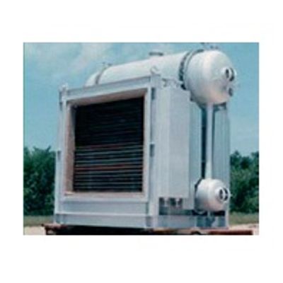
Garioni Naval - Model HRSG & WHRB -Exhaust Gas Boilers
Exhaust Gas Boilers HRSG WHRB EBG/OTSG; Building & Hospitals, Manufacturing Plants, Process Industries, Petrochemical Complexes, Pulp & Paper Plants, Utilities/Power Producers, Iron & Steel Mills, Tyre & Rubb er Factories, Chemical Industries, Sugar Refineries, Fertilizer Plants.
Most popular related searches
gas boiler
combustion control system
boiler exhaust
burner management control
combustion system
combustion controller
utility power
burner management
combustion control
burner management system
- PINCH POINT
- Approach Temperature
- LOAD TURNDOWN & CONTROL
- STEAM TEMPERATURE RANGE
- SYSTEM PRESSURE DROPS
- Operating Modes
- Firing Temperatures
- Staggered or inline Tubes
- Parasitic Loads
- Availability / Reliability
- Casing Design
- Material Selection (process and gas sides)
ACCORDING TO HEAT INPUT
- Unifired
- Supplementary Fired
- Fully Fired
- Fresh air fired
ACCORDING TO CIRCULATION
- Natural circulation
- Forced circulation
- Assisted circulation
ACCORDING TO NUMBER OF PRESSURE LEVELS
- Single Pressure / Low or High
- Multiple Pressure / Low or High
ACCORDING TO SOURCE AND HYGIENE
- Biomass, MSW, Solid Fuels, Coals, Prime Mover
- Clean or Dirty
ACCORDING TO PROJECT CONSTRAINTS
- Economy, Emissions, Timelines, Locations
- Combustion System:
- In Duct Grid Design
- Register Design (In Duct)
- Standards: EN-12952/NFPA/IRI/FMPitch
- Packaged Fuel Skids
- Scope Includes:
- Combustion Air Blower With Seal Air Damper for Fresh Air Firing.
- Silencer is Standard. (Standard Inverter Rated Motor/Optional VSD)
- Burner Management / Combustion Control System
- (S) Double Door Enclosure w/ Indipendent MCC & PLC Section
- (IP/NEMA) ; (IP 54/55 or IP 40 or Ex-Proof) a (O) Purge Control Unit (Ex-Proof)
- (S) Panel Air Conditioning Unit
- (S) UPS for PLC Control Section
- (S) BMS Interlocked with PLC
- (S) Touch Screen Control Panel With PLC (Optional Fail Safe PLC)
- (S) DCS/SCADA Communication Interface (Modbus/Ethernet/Profibus)
- (S) 3-Element Control System
- (S) Flow Metering with trending for Main Fuel, Steam, Feed Water
- (S) De-Salting Drum (Surface) Blow Down Control
- (S) Oxygen Trim (O2) Control (Fired Boilers Only)
- (S) Level Switches Based on Conductivity Probes (in addition to LT/Cap)
- (S) For Heavy Oils (Re-Circulation Control)
- (O) BMS Integrated into PLC (Economic Module)
- (O) Intermittent Blow-Down Control
- (O) Redundant Electro-Mechanical Reserve System (Controllers-Fuji/Yokogawa/Honeywell/Eurotherm)
- (O) De-Superheating Control (Attemperator or Diverging CV), Pressure Control Stations, Combi Stations
- (O) Automatic Soot Blowing Control (Steam or Sonic)
- Control Valves Samson or Arca or Koso / Fisher or Masonlienan
- Transmitters Fuji or Autrol/Ivensys or Honewell/Yokogawa or Rosemount
- Temp. Sensors/TT Comeco or Fuji
- Vortex Meters Krohne or Rheonik
- Gauges Nuvo Fima / Ashcroft
- Switches Danfoss or Sauter or SOR / Mercoid / Ashcroft
- Variable Speed Drives ABB or Yasakawa or Fuji/Danfoss or Schneider/LS Systems
- Level Control Switches Gestra or Mobrey / VYC or RTK / Clark Reliance
- De-Salting Control Gestra or Spirax / VYC or RTK
- Level Indicators Klinger / Bont or Diesse (LP)
- Electrical Devices GE / Terasaki or Green Power /Telemecanique or MG
- PLC System RENU or ICP-DAS (High Ambients)
- Siemens or Allen Bradley or Mitsubishi
- Fixtures & Fittings EU/USA/JapanOxygen Analyzers Ametek
- (Land Instruments)/Fuji/Client Specific
- Valves Kitazawa or Velan / Mival / Valvole Hoffman
- (LP) / DHV or Equiv. (Isolation & Drains)
- Feed Pumps SIHI or KSB (HP) / Grundfoss or Nocchi (LP)
- Dosing Systems LMI (LP) / Doseuro (HP)
- Safety Valves Tyco (Kunkle) / Leser
- Sampling Stations FM (Catch’n’Grab Stations are Standard)
- Fully Automated Water Analysis Stations on Request)
- DIVERTER, DAMPERS, GUILLOTINES, EXPANSION JOINTS
- FLUE GAS DUCTING
- Internal Lined (Insulated) in Carbon Steel With (O) SS Liners
- External Insulated/Uninsulated in Carbon Steel, Corten or Stainless
- DEAERATORS
- Pressurized (Tray or Spray)
- Atmospheric (Spray)
- FEED WATER PUMPS
- Turbine Driven
- Motor Driven
- DOSING SYSTEMS
- STACKS
Main and/or By-Pass External Insulated/Uninsulated/Lined in Carbon Steel, Corten or Stainless
- ELECTRICALS, INSTRUMENTATION AND CONTROLS
- NEMA/IP/Ex-PROOF
- CONTINUOUS EMISSIONS MONITORING SYSTEMS (CEMS)
- LADDERS & PLATFORMS
- AIR & FLUE HEATERS
- FUEL OIL HEATERS AND PUMPING SKIDS
- BLOWDOWN SYSTEMS
- SCR, SNCR, & CO Catalytic System (NOX/SOX CONTROL)
- ERECTION AND COMMISSIONING
- The approach is the difference between the economizer water outlet temperature and the Saturation temperature of the steam. A good approach point is between 15°F – 30°F.
- This temperature will guarantee that no steaming will occur in the economizer section.
- It is not always possible to achieve an approach point in this zone.
- If the saturation temperature is too high, achieving an approach temperature in this zone will lead to a stack outlet temperature well below the dew point, resulting in use of special steels to avoid corrosion.
Surface Area Pinch Is Used In Sizing Heat Of The Evap:
- The pinch point is the difference between the saturation temperature and the EVAP exit temperature
- It is desirable to make the pinch point as small as possible without making the cost of the EVAP astronomical