

Adon - Version EMS -Energy Software
Adon EMS our proprietary energy management system will maximize energy delivery and efficiency for each customer through providing intelligent load shifting, demand cost reduction, kWh savings and stand-alone power backups.
Our team at Adon Renewables has developed our own in-house Energy Management System software. When you purchase an Adon PowerBox battery, you will have peace-of-mind knowing your system is running at top efficiency.
Adon EMS saves you time and money by notifying you when issues arise, and it smooths out demand spikes through peak shaving.
Our Adon energy management system (EMS) provides monitoring and control of battery energy storage systems (BESS). The EMS pushes data from the battery system to either the onsite SCADA system or the cloud. Adon EMS provides the Operator real-time status information operation and state of the battery Operators need to make informed decisions. Additionally, the EMS can receive instructions from the Operator for various dispatchable and remotely configurable advanced grid support functions.
Communications can be either RS485 or TCP/IP. EMS data is crucial in helping quickly diagnose system maintenance issues as well as evidence for any equipment warranty claims.
The EMS also may be additionally configured to:
- Dynamically operate or curtail other onsite generators
- Act as the Operator in the event communication with the Operator is lost
- Operate the site in a stand-alone mode
- Provide demand response, provide time of use controls, manage power flow to prioritize energy use from a particular source
- Provide four-quadrant Utility grid-services or supplemental services to offsite systems (both DC and AC services)
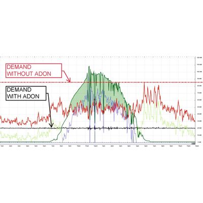
The EMS will obtain the cell and rack operation data from the BMS, and the operation parameters from the solar inverters, PCS, DC-DC converter, and energy meter. It also provides a user interface and graphical plots of the battery power, load, and net-load. A sample graphical plot and system parameters are provided below. The followings are the parameters that EMS monitors.
PCS:
- L1 AC Voltage (V)
- L2 AC Voltage (V)
- L3 AC Voltage (V)
- L1 Current (A)
- L2 Current (A)
- L3 Current (A)
- L1 AC Power (KW)
- L2 AC Power (KW)
- L3 AC Power (KW)
- Total AC Power (KW)
- Reactive Power (KVAR)
- PCS Potential Power (KW)
- Active Power Control Status
- Current Frequency Response Mode
- DC Voltage (V)
- DC String Current (A)
- DC String Power (KW)
Battery:
- Battery SOC (%)
- Battery SOH (%)
- Battery Max Charge Current (A)
- Battery Max Charge Voltage (V)
- Battery Max Discharge Current (A)
- Battery Min Discharge Voltage (V)
- Battery DC Voltage (V)
- Battery DC Current (A)
- Battery Alarm Status
- Basic Status
- Battery DC Power (KW)
- Battery Request Balance Charge Mark
- Battery Charge Forbidden Mark
- Battery Discharge Forbidden Mark
- Battery Request Force Charge Mark
- Battery Switch Value Indicate
- Battery Sleep Status
- Battery IDLE Status
- Battery Charge/Discharge Status
- Battery Cell Max Temperature
- Battery Cell Min Temperature
- Battery Cell Max Voltage
- Battery Cell Min Voltage
- Battery Cell Max Temp. Addr.
- Battery Cell Min Temp. Addr.
- Battery Cell Max Voltage Addr.
- Battery Cell Min Voltage Addr.
- Battery Module Max Temp.
- Battery Module Min Temp.
- Battery Module Max Voltage
- Battery Module Min Voltage
- Battery Module Max Temp. Addr.
- Battery Module Min Temp. Addr.
- Battery Module Max Voltage Addr.
- Battery Module Min Voltage Addr.
- Container Temp.
- Battery Cycle Times
Other Distributed Generators (PV, wind, diesel, etc):
- DG Source Power (KW)
- DG Source Status
Total Site (optional):
- Individal Load (KW)
- Net Load (KW)
- Net Reactive Power (KVAR)