

- Home
- Companies
- MRW Technologies, Inc.
- Products
- Open/Elevated Flare System
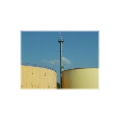
Open/Elevated Flare System
MRW Designs and manufactures the following elevated flare systems for all sizes and compositions of waste gas.
- Air-Assisted Flare Systems
- Steam-Assisted Flares
- Gas-Assisted Flares
- High-Pressure Flare Systems
- Staged Flares - Multi-Tip Flares
- Emergency Flares
- Back-Up Flares
- Industrial Flare Systems
- Process Flare Systems
- Utility Flares
- Smokeless Flares
- Ground Flares
- Pipe Flares
- Elevated Flares
- Open Flares
MRW open flare systems are guaranteed to meet EPA requirements for 40 CFR 60.18 and have a destruction removal efficiency (DRE) of 98%. If higher destruction is required, an enclosed flare system may be utilized if it is economically practical.
Our designs are based on experience with over 1,000 flare installations. MRW is a leader in flare system innovation and design, having supplied and installed successful, proven systems worldwide. From our use of modern structural and control techniques, to our proven flare tip and seal designs, MRW is committed to manufacturing the best flares built. We are able to accomplish this goal in part due to the following:
- MRW believes in safety first. Our flare system designs adhere to the strictest of safety standards.
- MRW Flare Tips are custom made and are of the highest quality.
- MRW Flare Pilots are designed for years of reliable, continuous operation.
- MRW proprietary Flame Retention Rings promote stable combustion and prevent lift-off at high exit velocities.
- MRW Purge Seals are designed for maximum efficiency and low operating cost.
- Prompt and reliable pilot ignition/monitoring systems allow for optimum performance of the flare systems.
- Our experience and relentless pursuit to keep our customers happy are unmatched in the combustion and flare industries.
Flares must always have a minimum heat content in btu/scf:
- Steam-assisted - 300 btu/scf
- Air-assisted - 300 btu/scf
- Non-assisted - 200 btu/scf
- Tip exit velocity is limited based on BTU content in the flare stream.
- Tip exit velocity is the velocity of the gas stream at the point where it exits the flare tip, not in the flare header itself.
Steam-assisted and non-assisted flares:
- 300 Btu/scf = 60 fps maximum
- Greater than 1,000 btu/scf = 400 fps maximum
Steam-assisted and non-assisted flares:
- Log10(Vmax)=(HT+28.8)/31.7
- Vmax=maximum velocity (m/sec)
- (note: never exceed 400 fps)
- HT=net heating value (MJ/scm)
Air-assisted flares:
- Vmax=8.706 +0.7084(HT)
- Vmax=maximum velocity (m/sec)
- HT=net heating value MJ/scm
Types of flare pilot monitors include (all flares must have a continuous pilot when in operation):
- Thermocouple
- IR scanner
- Video camera
Open elevated flare system testing:
- Sample at inlet to flare stack
- Measure flow rate to the flare
- Sample and determine Btu content
- 98% Destruction efficient by definition
Low BTU Gas - enrich before sampling point and prove enrichment by:
- Fixed ratio injection assuming 0 BTU content
- On line monitoring and gas control
Flare Stack Support Structure
- Self-Supported Stack
- Derrick Stack
- Guyed Wire Stack
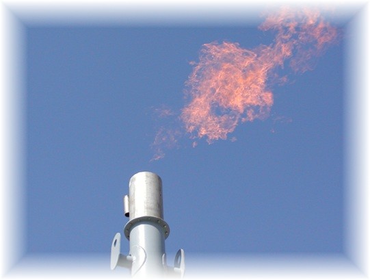
Flare Tips
- MRW Air-Assist Flare Tips
- MRW Steam-Assist Flare Tips
- MRW Gas-Assist Flare Tips
Pilot and Ignition System
MRW pilots and ignition systems are proven to be reliable, fast, and easy to operate and maintain. Our pilots are designed for continuous and intermittent use in adverse weather conditions and extreme wind speeds. MRW pilots increase the reliability and performance of the flare system by providing flame stability in any operating conditions. We are confident that our pilots are the absolute best in the world!
MRW designs extremely energy efficient pilots using as little as 50SCFH of fuel gas. The pilots are generally fabricated out of 309/310 stainless steel to extend the life of the pilot burner assembly. An air/fuel gas mixer attached to pilot burner assembly allows for a combustible mixture of pilot fuel gas at the pilot burner tip. Our local control panel powers the ignition transformers and automatically ignites/re-ignites the pilots.
Ignition of the pilot can be done via:
- Manual Ignition - the pilot is manually ignited via a push-button activation.
- Auto Ignition - a spark igniting device and ignition transformer ignites the flame front.
- Auto Re-Ignition - the flare tip pilot temperature switches automatically trigger the ignition transformers to re-ignite the flare tip pilots upon loss of flame.
- Remote Ignition - the flare system to be capable of automatic startup and shutdown based on either local or remote initiation.
Ignition of the pilots is accomplished using one of three methods:
- Flame Front Generator (FFG)
- Self-Inspirated Flame Front Generator (SI-FFG)
- Electric Spark Ignition (EFG)
Pilot Monitoring Device
- Thermocouple - MRW uses a proprietary thermocouple design and location to safely and accurately monitor the pilot status while also extending the service life of the thermocouples
- Flame Scanner
- Flame Rod
- Video Camera
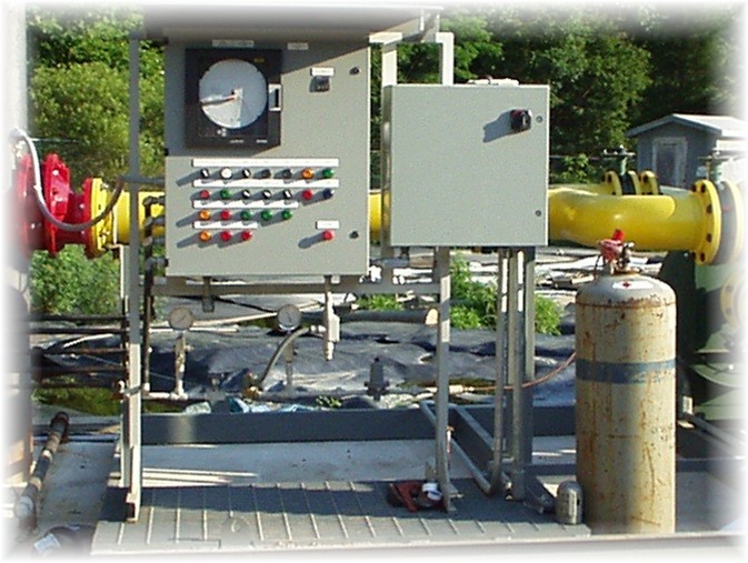
Control and Ignition System
MRW can design our control systems to meet any electrical classification. Our control systems utilize state of the art design techniques and technology to obtain optimum service potential. If you have a preference as to what type/brand of control system, we are happy to accommodate your needs.
Purge Reduction Seal (Optional)
- Molecular Seal
- Liquid Seal
- Velocity Seal
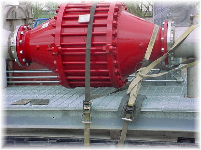
Flame or Detonation Arrestor (Optional)
In some situations, a flame or detonation arrestor is preferred or necessary. If a liquid seal cannot be used, gases are in the explosive range, and/or there are extended pipe runs or bends in pipe, a detonation arrestor may be used. MRW uses detonation arrestors are approved by the US Coast Guard.

Knockout Drum (Optional)
Knockout drums are provided in situations where liquid separation is likely in the waste stream. The knockout drum will collect any liquids that are present in the waste stream prior to entering the flare system. A knockout drum is especially important if substantial cooling of heavy liquids is expected. If the liquid is corrosive, MRW uses non-corrosive materials of construction. A level gauge and drain connections are built into the knockout drum.
Ladders and Platforms (Optional)
Access to the flare tip may be provided upon request from grade with OSHA approved ladders and rest platform(s) and one 360° access platform located just below the flare tip for easy access and maintenance of the flare tip.
Air Blower (Optional)
If assist air is required, an optional air blower will be included. The combustion airflow shall be automatically controlled based on waste gas flow rate to the flare. A flanged inlet and outlet as well as access door and housing drain is standard. Air duct is usually supplied from the fan outlet to the inlet of the flare stack.