

- Home
- Companies
- GreenPower
- Products
- BLAGO - Model TT - Pyrolysis Heat ...
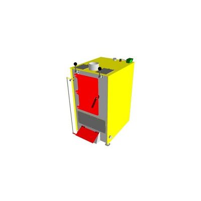
BLAGO - Model TT - Pyrolysis Heat Generator
Company Greenpower has been dealing with the development and production of thermotechnical equipment for more than 10 years. The company products became widespread in the CIS countries and beyond their borders as well.
Structure and principle of operation
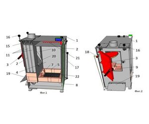
Pyrolysis heat generator with a frontal chamber of combustible gases afterburning contains case 1, water-jacket 2 formed in the case 1, doorset 3, fuel storage 4 situated in the case 1 over the combustion chamber 5, mechanism of air feeding into the combustion chamber 5 and combustible gases afterburning chamber 6, aperture 7 connecting combustion chamber 5 and combustible gases afterburning chamber 6, and ash chamber 8 situated under the combustion chamber 5.
Aperture 7 and chamber of combustible gases afterburning 6 situated under the bottom wall 9 of the doorset pass 3, and channels 11 installed behind the side walls 10 of the doorset pass 3 to discharge combustible gases out of the combustible gases afterburning chamber 6.
Mechanism of air delivery into the chamber of combustible gases afterburning 6 is produced from a through-hole 12 connecting the chamber of combustible gases afterburning 6 with ash chamber 8 and valve 13 regulating volume of air flow coming from outside.
Valve 13 combined with a plate of ash box 14 and section area of the through-hole 12 is regulated by the ash box 14 movement. Chamber 6 of combustible gases afterburning is lined with refractory material. At the same time the upper plate of refractory material in the chamber 6 of combustible gases afterburning is a bottom wall 9 of the doorset pass 3 and produced as detachable. Channels 11 to discharge combustible gases out of the combustible gases afterburning chamber performed in the water-jacket 2.
There are turbulence stimulators15 installed in the channels 11 connected to the linkage mechanism 16. Linkage mechanisms 16 are situated on the sides of the doorset 3 and meant for reciprocating motion of turbulence stimulators 15.
Due to reciprocating motion of turbulence stimulators 15 channels 11 are cleaned from ash, resins and tar. Ash chamber 8 has a fire grate 22. Fire grate 22 is cleaned by the stoking mechanism 17. Draught thermoregulator 18 is installed in the boiler water-jacket 2.
Draught thermoregulator 18 iis connected to the rotary valve 19 with a chain. There are scoop 20 and emergency cooling coil 21, fire grate 22.
Heat generator operation description
Pyrolysis heat generator with a frontal chamber of combustible gases afterburning operates in the following way. The door of the doorset 3 is opened. Dry woodchips are put on the fire grate 22. They are kindled. When woodchips inflames, firewood, coal or sawdust are to be put on it.
Then the door of the doorset 3 is closed. At the same time fuel storage 4 must be tightly closed. Feeding of the air flow moving to the combustible gases afterburning chamber 6 is preset. In order to do this, the edge of the valve 13 is installed in the middle of through-hole 12 passage section; ash box 14 is moved at the same time.
Final adjustment is based on the flame color in the combustible gases afterburning chamber 6, watching it through the inspection window. Flame must be of straw color in the optimal mode of fuel combustion. Scale in the draught thermoregulator 18 is set at 85 oC (for water) and rotary valve 19 – in the middle position. But it is not to be connected with a chain. When the temperature of coolant rises up to 85 oC (it is determined due to the readings of thermocouples) rotary valve is brought down allowing 3 mm clearance and connected to the draught thermoregulator 18 with a chain. Adjustment was done. Temperature of coolant changes during the process of fuel combustion.
Position of rotary valve 19 connected to the draught thermoregulator 18 with a chain changes proportionally. With a rise of coolant temperature lever of the draught thermoregulator 18 turns. As it is connected to rotary valve 19 with a chain, rotary valve 19 gets down closing the passage section of the ash box 8, through which air is drawn.
Air flow reduces as well as the oxidizing process with emission of heat energy. During additional fuel loading, air supply into the combustion chamber 5 and into the combustible gases afterburning chamber 6 is to be cut off by bringing the rotary valve 19 down until tight, open the door of the doorset 3 at the angle of 25-30 degrees, wait for 5 minutes and then completely open the door.
Rotary scoop is used to charge coal into the heat generator. Coal is loaded and with a rotation of scoop 20 up coal is loaded into the charging hopper 4.
- case
- water-jacket
- doorset
- fuel storage
- combustion chamber
- combustible gases afterburning chamber
- aperture
- ash chamber
- Bottom wall of the doorset
- side wall of the doorset
- channels to discharge combustible gases out of the combustion chamber
- through-hole
- valve
- ash box
- turbulence stimulators
- linkage mechanism
- stoking mechanism
- draught thermoregulator
- rotary valve
- rotary scoop
- emergency cooling coil
In our pyrolysis heat generators one can burn:
- wood, sawdust, wood chips;
- fuel briquettes, pellets;
- charcoal mixed with sawdust;
- tires and polymers;
- all possible combustible waste.
Heat generators are used to generate heat energy in the form of hot water up to 95 oC, hot air up to 250 oC, they can be applied for the heating and for technologic purposes as well (dryers, greenhouses etc.).
At our production facilities we started production of absolutely new solid-fueled pyrolysis heat generator - BLAGOtm adapted for our consumers and designed for our weather conditions, it confidently competes with foreign analogs and even surpasses them.
Combination of a lighting-up valve with a charging door improves fire safety of the boiler, prevents pyrolysis gases emission into the premises and its inflammation.
Major advantages of pyrolysis heat generators:
- Large loading chamber and doorway of the chamber.
- Bunker loading is sufficient up to 12 hours.
- Can run on bulk solids (sawdust, wood chips, pellets, husks etc.).
- Work due to both natural-draught and smoke exhauster.
- Full automatic operation and effective embedded system of protection.
- No manual control and gate valve of straight draught.
- Easy in cleaning.
- Plate-gas-tube heat exchanger.
- Air heating before feeding to the furnace and afterburning chamber.
- Made from high-quality materials.
- High coefficient of efficiency.
- Price-quality-characteristics ratio.
- Smokless fuel charging.
- Run on different types of fuel.
- Mobile variant is possible (for simplification of permission documentation).
Design description
Afterburning chamber, fire chamber and major part of the charging hoppers lined with refractory material. Outside the heat generator is heat-insulated with mullite silica mats.
In case of using polymers as fuel, heat exchanger is produced from acid-resistant steel that significantly prolongs its lifespan.
Remote vertical heat exchanger can be quickly cleaned and repaired as well.
There is a system of automation regulating heat generator operation in automatic mode. Heat generator is convenient for unscheduled repair. Any interfacing surface can be reached.