

Agni Power & Electronics Pvt. Ltd
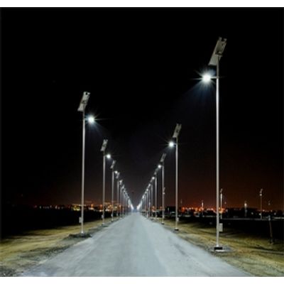
Agni - Solar Street Lighting System (SSLS)
The Solar Street Lighting Systems caters to need-based street lighting and outdoor/garden lighting. It gives 10-12 hours of continuous, bright, cooler light, with automatic dusk to dawn controls. A typical SSLS comprises of a CFL/LED luminary light source, battery (LMLA/VRLA) for storage of electricity, PV module for charging the battery, charge controller for safe charging and discharging of battery and dusk-to-dawn controls for operating the lamp. The system is tested as per MNRE technical requirements/standards.